Monday, 17 February 2025

A floating point test for Arduino


How to choose the Arduino MCU for fast and double precision data processing

Giovanni Carrera, 17/02/2025

In some applications it is necessary to perform calculations in double precision, such as in the coordinate conversion of a GNSS receiver. This problem arises when I want to interface a satellite receiver with Arduino compatible boards.

At the moment it seems that floating point calculations performed with MicroPython are single precision only.

Google Maps wants the latitude and longitude in decimal degrees, so it is necessary to extract the substrings of the prime minutes from the coordinates of the NMEA sentences, and convert them into float numbers and then in tenths of a degree.

Operating with single precision variables, that is with 6-7 significant digits, you get about five decimal digits on decimal degrees, this leads to a horizontal resolution of about one meter, lower than 
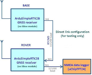
the error of a common GNSS receiver. But if I want to do statistical calculations or work with RTK receivers this resolution is no longer acceptable. The RTK differential receivers, that work on the carrier phases, have a centimetre accuracy and provide the coordinates with 6-7 decimal digits on minutes, like the ones I used in my program. For these considerations it is necessary to use an MCU (Micro Controller Unit) that has a true double precision math.

For some MCUs it is not always clear how the floating point arithmetic is actually calculated, so I wrote a test program for the conversion from degrees and minutes in decimal degrees.

First I wrote my program on PC, in Matlab which operates in double precision. I started from the coordinates expressed in string, I convert the degrees and minutes into numbers, then in decimal degrees.

Lats = '4221.0081996';

Longs = '01321.4740622';

lat = str2double(Lats(1:2)) + (str2double(Lats(3:end))/60);

long = str2double(Longs(1:3))+ (str2double(Longs(4:end))/60);

fprintf('latitude    = %s \n',Lats);

fprintf('longitude   = %s \n',Longs);

fprintf('latitude (dec)  = %12.9f°\n',lat);

fprintf('longitude (dec) = %12.9f°\n',long);


With the coordinates indicated it gave the following results:

latitude    = 4221.0081996

longitude   = 01321.4740622

latitude (dec)  = 42.350136660°

longitude (dec) = 13.357901037°


So I wrote the following Arduino IDE program to evaluate the numerical results and processing times of the various MCUs on which I performed the test.

/* program doubletest.ino

 test double precision of MCU

 Giovanni Carrera, 14/10/2019*/


const String Lats = "4221.0081996";

const String Longs = "01321.4740622";


void setup(void) {

  Serial.begin(115200);

  while (!Serial) {

    ; // wait for serial port to connect

  }

  delay(100);

  Serial.println("MCU double precision test");

  // convert Lat&Long in decimal format

  unsigned long  ti= micros();

  String minuts = Lats.substring(2);// latitude minutes

  double minutes = minuts.toFloat();// convert it to float

  double decdeg = minutes/60.0;

  String Latdegs = Lats.substring(0,2);

  double Latd = Latdegs.toFloat() + decdeg;// latitude in decimal format (double)

  minuts = Longs.substring(3);// longitude minutes

  minutes = minuts.toFloat();// convert it to float

  decdeg = minutes/60.0;

  String Longdegs = Longs.substring(0,3);

  double Longd = Longdegs.toFloat() + decdeg;// longitude in decimal format (double)

  unsigned long  tf= micros();

  Serial.print("Latitude (dec)  = ");

  Serial.println(Latd,8);

  Serial.print("Longitude (dec) = ");

  Serial.println(Longd,8);

  Serial.print("elaboration time [us] = ");

  Serial.println(tf-ti);

} // end of setup


void loop() {

}


I tried this program also on 8 bit processors like the Arduino Uno to verify that the double precision is simulated and also on Teensy v3.2 that mount a 32-bit MCU type ARM Cortex-M4 at 72 MHz but that does not have a true 64-bit mathematics. So I narrowed down the study to six types of MCUs that yielded the same numerical results.


ESP8266

This module uses a 32-bit MCU clocked at 80 MHz. I ran the test program on a ESP8266 type Wemos D1 mini which features an ESP-12F module, with the results:

MCU double precision test

Latitude (dec)  = 42.35013666

Longitude (dec) = 13.35790103

elaboration time [us] = 388

Correct numerical results even if processed with relatively high times.


ESP32

This interesting and versatile module uses a single/dual-core 32-bit LX6 Xtensa MCU clocked at up to 240 MHz. I ran the test program on a Node MCU development board with ESP32 WROOM.

MCU double precision test

Latitude (dec)  = 42.35013666

Longitude (dec) = 13.35790103

elaboration time [us] = 152

Numerically correct values with very good processing times. I also obtained similar results with an ESP32 WROVER.


Arduino Due

I used an original Arduino board, the first to mount a 32-bit processor, using an Atmel SAM3X8E ARM Cortex-M3 clocked at 84 MHz.

MCU double precision test

Latitude (dec)  = 42.35013666

Longitude (dec) = 13.35790103

elaboration time [us] = 141

Correct results and with the best execution times.


Arduino Zero

For this test I used a Maduino A9G board, an Arduino Zero compatible, which mounts a 32 bit MCU type ATSAMD21G18 clocked at 48MHz and an A9G module that combines a GPRS / GSM terminal and a GPS / BDS satellite receiver on which I developed also a data logger program for satellite data

MCU double precision test

Latitude (dec)  = 42.35013666

Longitude (dec) = 13.35790103

elaboration time [us] = 250


Teensy 4.0

Teensy 4.0 has a 600 MHz ARM Cortex-M7 processor, an NXP iMXRT1062 chip, and is the fastest microcontroller available at the moment.

MCU double precision test

Latitude (dec)  = 42.35013666

Longitude (dec) = 13.35790103

elaboration time [us] = 5


Arduino Uno R4

This recent board mounts a Renesas R7FA4M1AB3CFM#AA0 processor type Arm® Cortex®-M4. at 48 MHz.

MCU double precision test

Latitude (dec)  = 42.35013666

Longitude (dec) = 13.35790103

elaboration time [us] = 184


Conclusions

The following table summarizes my test results.

board

MCU

CPU clock [MHz]

time [µs]

Arduino Due

Atmel SAM3X8E ARM Cortex-M3

84

141

ESP32 WROOM

Xtensa single-/dual-core 32-bit LX6

240

152

Arduino Zero

ATSAMD21G18

48

250

Wemos D1 mini

ESP8266EX, Tensilica L106

80

388

Teensy 4.0

ARM Cortex-M7

600

5

Arduino Uno R4

Arm Cortex-M4

48

184

The system that gave the best results is Teensy 4.0, followed by Arduino Due, which I had already used in the past for GNSS RTK data processing. Considering the performance/price ratio, the ESP32 is certainly the best system.


Monday, 3 January 2022

ZED-F9P RTK Receiver Test Measurements

The results of numerous tests carried out using ArduSimple RTK2B-V3 boards are presented
 Giovanni Carrera, 03/01/2022


Introduction

Since the Ublox ZED-F9P GNSS RTK module came out, there are many boards on the market that use it. I have had the opportunity to test the ArduSimple RTK2B-V3 board for a long time with results that I will now describe.

I have performed numerous tests, static and dynamic, to verify the operation and also the connection and the development of firmware of the systems that I have made with 32-bit microcontrollers. I used the ArduSimple RTK2B-V3 board with G4 module for receiving RCM3 messages from a reference station with NTRIP and I also connected the Base-Rover stations directly to see the highest possible accuracy.

The results, as we will see later, were very good even if the operating sites available don’t have the maximum visibility of the sky and the distance to the reference station was quite high.


The Ublox ZED-F9P module

The ZED-F9P module can receive and track multiple GNSS  constellations: GPS, GLONASS, Galileo and BeiDou plus SBAS and QZSS satellites as shown in the following table.

GPS

GLONASS

Galileo

BeiDou

L1C/A (1575.42 MHz)

L1OF (1602 MHz + k*562.5

kHz, k = –7,..., 5, 6)

E1-B/C (1575.42 MHz)

B1I (1561.098 MHz)

L2C (1227.60 MHz)

L2OF (1246 MHz + k*437.5

kHz, k = –7,..., 5, 6)

E5b (1207.140 MHz)

B2I (1207.140 MHz)

All satellites in view can be processed to provide an RTK navigation solution when used with correction data. It has a USB interface, two UART ports and also I2C and SPI interfaces.

The ZED-F9P position accuracy in RTK mode, is at the centimeter level, as confirmed by the numerous tests I have done.


The RTK2B-V3 board

ArduSimple RTK2B is a very compact and versatile board. In addition to the ZED-F9P module, it also mounts an Xbee-type connector complete with a USB/TTL adapter and a second USB port for its programming.

ArduSimple manufacturer supplies a series of modules to be mounted on this interface for radio communication such as Bluetooth, G4, WiFi, Lora, etc.

Figure 1 shows the board, whose dimensions are similar to that of Arduino Uno/Zero, to which it is perfectly compatible.

Figure 1

The I/O signals are 1.8V, 3.3V and 5V compatible, adjusted automatically on IOREF voltage.

This board can be powered directly from the Arduino headers or via a micro USB connector and is protected against double power source (header and USB). The power consumption, without Xbee modules, is about 200 mW. The board is equipped with a high power, low noise LDO (Low Drop Out) regulator. With only 390 mV dropout it is possible to power the board with a single  Li-ion cell.

Numerous on-board LEDs indicate to the user the operating status of the system.

The board has a connector compatible with ArduPilot systems for high accuracy position control applications.


RTK tests with NTRIP

The first tests were carried out with the correction sent by a reference station of the Ligurian Regional GNSS Network via NTRIP, using first the PC with U-Blox U-Center software, then a G4 module on the ArduSimple Xbee slot. The connection via PC to the internet allowed to better test the NTRIP configuration.

NTRIP (Networked Transport of RTCM via Internet Protocol) is a protocol developed by the Federal Agency for Cartography and Geodesy of Germany (BKG) in late 2004 that allows for the streaming of DGPS or RTK correction data via the Internet. With a personal computer or mobile phone supporting TCP/IP, NTRIP is the best way to send RTCM messages to the rover RTK receiver without having to use an expensive local radio, which to comply with radio communication laws, they are low power and therefore short range.


The 4G LTE module

The G4 module used is a Telit model LE910 V2. Whose bands, for Europe, the Middle East and Asia, are:

·         4G Bands (MHz): B1(2100), B3(1800), B7(2600), B8(900), B20(800)

·         3G Bands (MHz): B2(2100), B8(900)

·         2G Bands (MHz): B3(1800),B8(900)

This module is mounted by ArduSimple on an Xbee compatible board whose appearance is shown in figure 2.

Figure 2

This module requires high power (HP) and must be mounted on RTK2-V3 type boards.

For its configuration I followed the instructions of the hookup-guide [6] to which I refer the reader.

The functional scheme is shown in figure 3.

Figure 3


I have chosen NEAR3 as the Mount Point.

To achieve a high resolution, High Precision Mode must be configured. In this way latitude and longitude therefore have seven digits after the decimal point and the altitude has three digits after the decimal point.

Connect the Rover to the PC and start the U-Center program, from the 'Configure' menu set 'NMEA protocol' and click on 'High Precision Mode' and then save the configuration.

I have assembled all the components of the Rover in a box, as shown in figure 4.

Figure 4


In this case I used an ATmega328P based OpenLog system to save the corrected NMEA sentences from the RTK receiver to SD. In some tests I used a much more performing system (uChipTFT24), purposely designed by me, based on the SAMD21 MCU with 2.4 inch TFT touch screen with inbuilt SD card slot, as shown in figure 5.

Figure 5

I have also developed software on this system that also calculates the UTM (Universal Transverse Mercator) coordinates, shown on the display along with other information, such as the fix quality index.


Fixed point measurement (NTRIP) #1

The measurements saved on a SD card, have been processed in Matlab on a PC.

Here are the outputs of my programs:


File name        = LOG00013.mat

Values averaged on 551 epochs, from point = 1, to point = 551

Initial GPS time = 32779 and final = 33329

CEP R95          =    0.010 m

Figure 6

The CEP95 is a very valid index of horizontal accuracy: it is the radius of the circle that contains 95% of the measurements.

Plotted measurements refer to a time interval where HDOP was minimal, as seen in figure 6. However, the fix quality index was equal to 4 (fixed ambiguity solution) for the whole recording, confirming its good quality.

Although the reference station is 16 km away and there is no complete visibility of the sky, the results are excellent.


Fixed point measurement (NTRIP) #2

This measurement was made on top of a mountain, therefore in a site without obstacles, unlike the other measurements which were always made in mountain locations, but with some obstacles. Also here I was closer to the reference station GENU (about 6 km).


File name       = 01092109.mat

Values averaged on 280 epochs, from point = 174, to point = 453

Initial GPS time = 32973 and final = 33252

average latitude  = 44.458543193°

average longitude =  9.067446390°

Elevation       = 755.25 m

CEP R95         =    0.006 m

Figure 7

I have included this test to show how important it is to have coordinates with many significant digits. In this case my system saved the coordinates with 8 decimal digits which brought a resolution to 0.8 mm on the West-East axis and from 3.3 to 4.4 mm on the South-North axis. Later I modified the program to save the coordinates with 9 decimal places and things have improved a lot.

Despite its relative low resolution, the results were good, with a CEP95 measuring just 6mm.


Rectilinear motion at constant speed

I also wanted to make a dynamic measurement: to have a precise spatial reference, I made the rover antenna move along a straight rail with constant speed.

To do this test I made a special device. An aluminum profile creates a rail on which a wooden shoe slides pulled by a rope and a pulley moved by an electric gear-motor. The figure 8 shows the gear-motor and the tow pulley on which I made a double turn of the cable.

Figure 8

Here are the outputs of my Matlab program:

File name         = 30082107.mat

Values averaged on 29 epochs, from point = 309, to point = 337

Initial GPS time  = 26030 and final = 26058

Path traveled     =    1.678 m

Mean speed        =   0.0599 m/s

Figure 9

The red line, in figure 9, was drawn between the average of the start and end points measurements.


Fixed point measurement (direct link)

This test of the receivers excludes the transmission system of the correction data transmitted by the base, replacing it with a simple wire, as shown in the figure 10.

I mounted the two boards and the serial data logger in a single case, as shown in fig. 11.

I configured the two units with the base and rover configuration files.


Figure 10

Of course this is the system that should give the maximum accuracy precisely because the two antennas are a few meters apart and there are no radio link disturbances.

The Rover must be configured for NMEA output at 115200 baud.

It is necessary to configure the Tx1 output of the Rover for the NMEA protocol in High Precision Mode (coordinates with 7 decimal digits). The data logger used for this test was an OpenLog type system.
Figure 11

The following table shows the configuration of the switches on the two boards.

switch configuration

ArduSimple V3 Base

ArduSimple V3 Rover

Swirch#1

XbeeTo GPS UART1

XbeeTo GPS UART1

Swirch#2

IOREF& 5V ARE INPUTS

IOREF=3V3, 5V = OUTPUT


ArduSimple Base-Rover wiring

Base

Rover

Tx1

Rx1

Rx1 not connected

Tx1 to logger

5V (input)

5V (out)

Gnd

Gnd

IOREF (input)

IOREF (3V3 out)

USB not connected

USB connected

Arduino rails are used for wirings.

USB is connected to Rover for powering and PC monitoring of  the system.

Here are the outputs of my Matlab program:

GNSS measurements

File name       = LOG00014.mat

Values averaged on 578 epochs, from point = 1, to point = 578

Initial GPS time = 42023 and final = 42600

CEP R95         =    0.007 m

Figure 12

References

1.       “ZED-F9P u-blox F9 high precision GNSS module data sheet”, UBX-17051259- R08, www.u-blox.com, 04-Jun-2020.

2.       “ZED-F9P u-blox F9 high precision GNSS module Integration manual”, UBX-18010802 - R08, www.u-blox.com, 02-Jun-2020.

3.       https://www.kickstarter.com/projects/simplertk2b/simplertk2b-the-first-multiband-rtk-shield-based-o

4.       https://www.ardusimple.com/simplertk2b-v3-hookup-guide/

5.       https://www.ardusimple.com/product/simplertk2b-f9p-v3/

6.       https://www.ardusimple.com/4g-ntrip-client-hookup-guide/

7.       https://www.ardusimple.com/configuration-files/

8.       “Logger GPS con UCHIP”, Giovanni Carrera, ‘Elettronica In’ magazine, n. 257, september 2021